


porc
-
Posts
99 -
Joined
-
Last visited
Content Type
Profiles
Forums
Gallery
Everything posted by porc
-
a normal heat sink definitely works differently from a peltier. it's also different compared to blowing a fan onto the water surface. The driving force for evaporative cooling is humidity difference. the water surface is at 100% humidity while the environmental air is less. therefore the environment attempts to pull water vapour away from the 100% humidity area on the water surface, and in turn the air on the surface pulls water vapour from the water itself. In order for the water to become water vapour it pulls heat from the surrounding water molecules and that is the reason why your tank cools down. For a heat sink the driving force is temperature difference. there must be a temperature difference between the block and the surrounding air before heat transfer can occur. And in singapore if the air temp is 30deg and your tank is at 26deg, a normal heat transfer block will actually be transferring heat into your tank, no matter how hard your fan blows. In fact, turning the fan up will further increase the rate of heat flow into your tank. so in simple terms a normal heat sink may not work, especially in singapore... cheers...
-
2-wks already... it must be hungry. The puffer may not recognize the prawn cubes that you're feeding now as food. Try some ghost-shrimp first. It'll be more interested in live, moving objects. Then later when the fish realises that what you're putting in is food, then you can switch back to your current prawn cubes... oh yah... if the ghost-shrimp 'siam' too fast or gets eaten by your other fish, you can also try using a pair of chopsticks to hold on to the shirmp in front of the puffer... my own experience lah...
-
Hi, for a UV sterilizer you should be more concerned about your pump being too strong rather than too weak... you would want to maximize the time the water spends in the chamber being blasted by the UV rays... When I used one previously (china brand) the box even stated not to exceed flow by a certain amount. Calculating based on the flow rate you stated (20 gal/hr/watt) is not accurate at all. there is no information on the volume capacity of the sterilizer itself. eg. suppose your uv sterilizer is 20 gal then every molecule of water is exposed for 1 hr, but if your sterilizer is 1 gal volume that water only stays inside for 3 mins... I don't know what should be the flow rate. I guess maybe turning around your tank's capacity every hour or even 2 hours should be fine. Cheers, porc
-
I'm interested in the tank and cabinet only. Bro dtoh, wanna combine order? check your pm. cheers, eddie
-
Curious too.. has anyone ever tried those japanese white sponge/foam like thingy which claims to be able to wash dishes without soap. Used to have those product demonstrators around the housing estate centrals showing how to use it. Think it's also suppose to be antibacterial but would it be harmful to the tank?
-
some comments... the weakest link in the whole structure now seems to be at the point where you screw into the wood and metal. if this part fails the reinforcement is useless. you mentioned that the stand is already beginning to rust. from now on the place that you have screwed is going to be where it's gonna rust most, due to the redox differences of the 2 metals (jc chemistry). this will excerbate point 1 above. Since you already have the wood for 6 legs, I suggest you add some horizontals (screw or nail wood to wood) so that the wood part itself is some sort of stand-alone structure to help support the weight.
-
Hi Giantbicycle, Sorry to here of your flooding incident. Glad everything is ok. Guess we all just have to beware of how we set up our tanks, making sure that nothing is loose or leaks. But accidents still do happen which sometimes cannot be prevented. But we must not give up... Anyway, some comments about the stickyness of the floor. It's due to the drying up of water leaving behind salt on the floor. Not too sure how the vinegar or detergent may help, but essentially what also needs to be done is basically to redissolve the salt and clean it up, which is very slow when you simply use a damp mop and small pail of water and mopping around. you're simply redistributing the salt... It will be faster to wet the floor again by pouring more freshwater directly onto the floor (in a controlled manner lar, like maybe a cup at a time), soaking it up quickly with a mop or cloth, then squeezing the water out and throw away. Of course this is provided you have a stone flooring... Works for me... Cheers...
-
somehow my toolbar for the straits times page says 1 dead 17 injured but the page still reloads as 5 missing 15 injured...
-
Cool bro... congrats... but you have an extra pump on there generating heat now... maybe that's the reason... hehe... this one totally way out of my field...
-
basically what your adapter reads is that it provides 12V and up to 120mA output. you need to read what's on your fan too. My fan at home says DC 12V 0.13A. note that 0.13A = 130mA. So if I use your adapter with my fan, the voltage is compatible but my fan will draw more current than your adapter can handle, thus may overheat the adapter (BAD!) You can try to find a 500mA or 0.5A adapter. That can handle up to 3 of my fans (130x3=390mA) connected in parallel safely. Hope this helps...
-
Good read... but the contact time between water and air bubbles is also important right? No point having a high turnover rate but a small chamber volume such that the contact time is very small. I guess the well designed skimmers would have taken this into consideration, but what's the actual recommended time. Anyone read something on this before? I guess this info will be useful too for DIYers... cheers...
-
yup. it's in this latest thread.. http://www.sgreefclub.com/forum/index.php?...opic=15530&st=0
-
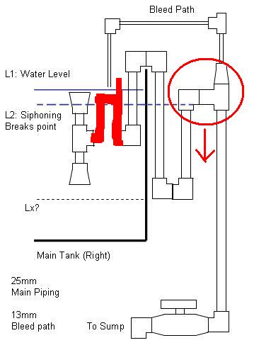
yes, i agree that under normal failure water will drop only till break point 1. Looks like we are in agreement on this and you are good to go... It's not you lah... It's the damn ease of access of the internet and this site. I specifically withheld myself from coming in last night (so that I can sleep early cause I need to work hard today) and this morning but by lunchtime, beh tahan already... See! now I'm back in again, but at least I finished my work for today... guess we're bitten by the reefing and diy bug to think of solutions to all these challenging problems... just as I thought. so technically speaking it's not that the flow rate that is slow. it's just that insufficient height has been built up to increase the flowrate. For my one at home the L1-L2 height difference is only about 3 cm, but I guess this will change depending on your pipe size and flow rate. true! you have the spirit and determination man... i simply gave up on the bottom intake spec when I made mine... Last time I saw it costs enough to build me 10 overflows... cheerios
-
consider this mod to your new design... haven't thought in detail... you can help think thru whether this will work.. lower the second bend and add the pipes in red. water level in tank will drop to same siphon break point as indicated, but water level in the red pipe will drop to L2. arrggh.... this is distracting me from my work... okay last post for now... will be back tonight... further edit: damn!. just realised this design is no different from yours, only structually different in terms of piping. think I get your idea now... I still think water level will not drop below siphon break point 1, but with this you can increase the L1-L2 difference without emptying the main tank. brilliant!!!
-
Hi Desmonds, Sorry to hear of your unsuccessful attempt . Puzzles me why you would experience low flow rate. Has the tank level stabalized yet? Or is it that you found that your overflow is not coping with return flowrate and you had to abort the test before your main tank overflows? If this is the case then yes we may have allowed for insufficient L1-L2. All the way man... that's the spirit... I do not have time now to fully analyze your diagram and figure out what you are trying to achieve. But from a quick glance it seems that the water level will not fall below siphon break point 1. Maybe tonight I'll get back to this. Cheers...
-
hi , basically your design is equivalent to a full siphon overflow, the flow through the canister will continue even if the canister pump stops (assuming there is no check-valve involved). This is something that has been discussed in at least 2 other threads over the last few days here in the DIY section. There, we were discussing the design with control valves to control both the return and siphon pipes so that the flow rates in and out of your tank are equal. but in your case you do not have any control valves and your siphon in fact has a pump pushing the water through... so although your design is conceptually workable, it is incapable of being tuned, and unless you are really lucky (i mean really really lucky.. hint hint... ) your design won't work for more 2 minutes... think about it... suppose your return pump is 1200 l/hr and your canister pump is 1000 l/h, or the other way round... what will happen? and even if you add the control valves to make it tunable, i would say that the "full siphon" overflow is still a more risky design which may be prone to runaways. some of the scenarios that could happen have been described above and also in the following thread http://www.sgreefclub.com/forum/index.php?showtopic=15023 . i would recommend an overflow system like an I-box or a diy one as I mentioned in the other threads whereby there's no need to control anything. the main design advantage here is that whatever you pump back to the main tank will automatically flow down to the sump. with this design you can even reuse your canister as a closed loop in the main tank and increase circulation. as for the flood control allowances there's no escaping it. but the "uglyness" of having the allowance space can be minimize by the placement of your pumps and outputs. let's take your example. your main tank is 2ft x 1.5ft x 1.5ft and your sump is 2ft x 1.5ft x 2ft(ht). suppose your "ideal" water level is 1.5" (less than 4cm, still reasonable right??) below the top of your tank and your return piping outlet is 1" below your water level. so if your return pump fails 30 x 18 x 1 = 540 cubic inches of water will flow back down to the sump, which means you need at least 540/(24x18)= 1.25" empty height in your sump. And you are not allowing your sump to fill to the brim right? so if you give an extra 1" allowance, your sump water level can be 2.25" (5.7cm) from the top of the sump. it's a sump anyway and 2+ inches out of 2 ft height still gives you plenty of space for your dsb and microalgae. but your placement of return pump must be calculated soo. If you place your return pump inlet 1" below the sump water level, when your overflow somehow fails you will pump at most 24x18x1=432 cubic inches back to your main tank, which works out to be an increase of 432/(30x18)= 0.8 inches in your main tank. but remember yur "ideal" operating tank level is 1.5" below the top as assumed earlier, so no problems here too... hope this helps.. do ask more questions if you have any... fire away!!! cheers...
-
Hey bro rockfish, Thank you for your strong reply... got me thinking again why we are having so different opinions on the designs... I realised that maybe our assumptions may have been different in the first place... My assumption is based on an overdesign in the piping sizes... so bigger pipes, less friction, less pressure difference required. so not neccessary to lower the second bend. This assumption might not be there in your recommended design, so with a higher flowrate with same or smaller piping, yes you do require more pressure difference, which you would then need more height in your tank for the equilibrium tank level to be achieved if you simply use the design given by bro domino, or to use the skimmer tube as you mention... Could you share with me your experience in using the earlier design? When you say that you find the flowrate slow, has the equilibrium tank level been achieved yet? or is it that you find the water levels still increasing but the siphon is still unable to cope with the flow so you decided to stop before your main tank overflows? Cheers...
-
please go look into your skimmer column and see what is the water level inside that...... sigh... again...
-
sigh...
-
great idea on the bleed path! Lx does not matter, but do try to eliminate/minimise bubbles creeping into the siphon bend by having as long a tube as possible for the piping just below the skimmer's "expanded" intake. I also suggest the following building procedure. don't fix the skimmer input and tubing to the t-joint first. Run your full system and see where L1 stabilises to. then measure the length of the pipe required such that the skimmer is just below the water surface... Your design seems real good now. Let us know when it's done and working. All the best!!!
-
just to add, you would need to have a hole (see red arrow on diagram) to allow air into that portion of the bend, otherwise a full siphon might develop and it's no different from the earlier design. post_9_1082017456.jpe
-
Parts Per Million (PPM) - A unit of concentration often used when measuring levels of pollutants in air, water, body fluids, etc. One ppm is 1 part in 1,000,000. The common unit mg/liter is equal to ppm. Four drops of ink in a 55-gallon barrel of water would produce an "ink concentration" of 1 ppm.
-
no probs.. cheers...
-
the air will not flow out by itself. you have to suck the air out. let me explain the procedures. 1) stick the input of the siphon into the water. 2) cover the output of the siphon ie. place a plastic bag over the output and use rubber band to hold it in place. 3) open the air valve and start ###### the air out. 4) when water begins to be sucked out of the air valve, shut the air valve. 5) remove the plastic bag and your siphon will start immediately...
-
I think he mentioned that he already has holes drilled into the tank. In that case he has a direct overflow and not a siphon overflow. We precisely do not want to drill our tank for fear of breaking it, so his solution is not suitable for us...