


-
Topics
-
-
Latest Update
-
1
-
2
Wts redsea light hanging rack 3ft
Below 2 racks also included. I was thinking to remove this post because the price above not correct. -
0
Wts coral
4 item all for $170 92328813 wa for more photo Collect @ toa payoh VID20240606222319.mp4 -
2
Wts redsea light hanging rack 3ft
Hi pmed Sent from my iPhone using Tapatalk -
1
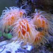
Dismantling Tank
Hi, the clownfish have now sold. Selling everything else left, so the anemone, 1 sixline wrasse, 1 tomini tang, 3 chromis, 1 blue legged hermit crab, 1 kuekenthli shrimp, a few nassarius, trochus and mexican turbo snails for $80. Once thats gone, then the rock and tanks.
-


Recommended Posts
Join the conversation
You can post now and register later. If you have an account, sign in now to post with your account.