


-
Topics
-
-
Latest Update
-
0
wts corals
clearing the following for space - cyna 15 - multi colour lobo 30 - some assorted zoas 20 - red acan 15 - bowerbanki 30 3 heads - torches 15 each - hammers 20 pr head on pm if interested or whatsapp 88604nine64 selling at lowest price just for clearance -
0
Decomm Equipment Sales
Selling the following, self-collection at pasir ris. PM for more info. BUBBLE MAGUS EXTERNAL NANO SKIMMER (BM-QQ1) Selling at $58 (retail price $98) DYMAX SPACEX LIGHT Selling at $90 (retail price $153) EHEIM classic 250 External Filter Selling at $90 (retail price $159) (NO TUBING) Hailea HS-28A 1/10HP Selling at $250 (retail price $410) pm here or msg me on telegram @mariokirby. -
96
-
197
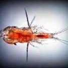
WTS live rotifers, tigger pods, phyto
Loc at hougang/tamp Tele me at littlefishaqua Sent from my 22101316G using Tapatalk -
0
-


Recommended Posts
Join the conversation
You can post now and register later. If you have an account, sign in now to post with your account.